Creating and Editing Data Flow Edges for DPUs in UnifiedViews
Creating and Editing Data Flow Edges for DPUs in UnifiedViews
This section contains a short guide on how to create edges between DPUs on the canvas in UnifiedViews.
You can create edges this way:
Create data flow edges by clicking on the Create new edge icon on the DPU instance tool bar.
Drag your mouse to the DPU you want the edge to connect to and click inside that DPU's instance.
Note
After every modification of the graph edge, the application needs to verify if there is no cycle in the graph, and to deny the modification if there is one.
Find details on how to edit DPU edges in this topic: Edit DPU Edges
Edit DPU Edges
Edit DPU Edges
This section contains a short guide on how to edit existing DPU edges and creating mappings between output and input data units.
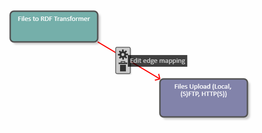
Every edge has a tool bar that appears after clicking on the edge.
Click the Edit edge mapping icon to open the Edge Detail dialogue.
The Edge Detail (1) dialogue allows you to map output data units to input data units.
The dialogue contains a list of Output data units of the source DPU (2), which is a source of the edge and a list of Input data units of the target DPU (target of the edge, 3).
The application will find out the provided output/input data units via annotations.
To map Output data units of the source DPU to Input data units of the target DPU use the Edge Detail dialogue.
Select one or more output data units.
Select one input data unit.
Click Map.
The dialogue must check that at least one output data unit and exactly one input data unit have been selected.
As a result, a new mapping appears in the Available mappings area, one row represents one mapping.
You can delete a created mapping and also clear the selection of the data units to be mapped.
Click Save to confirm your changes or Cancel to abort.
For example, the Edge Detail dialogue contains the following parameters:
Output data units of the source DPU:
rdfOutput
Input data units of the target DPU:
config
input
On the left, select rdfOutput, on the right select config. Click Map to create the mapping.
Click the Save button and on the pipeline canvas the mapping will be visible on the edge: